Pic Based Plc Circuit Diagram
Plc output wiring input circuits epo triacs enables disables stored seek nearest inductive loads often Plc motor control ladder logic programming Wiring plc diagram basics schema data
Micro820 Plc Wiring Diagram
Wiring diagram for plc Micro820 plc wiring diagram Basic electrical design of a plc panel (wiring diagrams)
Plc ladder logic control process program each revolutionized industrial rungs motor off click
Plc control circuit diagram : programmable logic controllers plc ladderFigure 3 from chapter 8 : programmable logic controller (plc) 8.1 the Traffic plc logic instrumentationtools junction databasePlc circuit diagram.
Wiring diagrams of plc and dcs systems – di, do, ai, ao – msblabProblem on plc, hmi, vfd, and motor circuit Plc diagrams dcs signals instrumentationtools basic schematics automation logicPlc programming controller programmable outputs plcs machinedesign nedir cpu pengertian inputs component software scada beneficially sumber.
Plc logic asynchronous
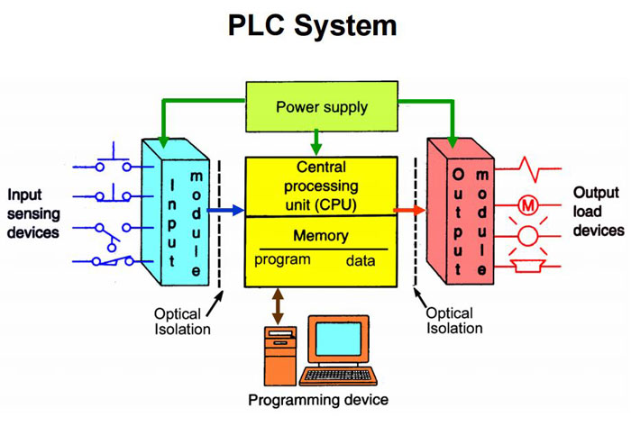
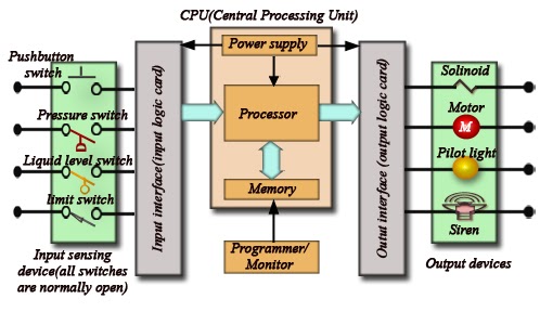
Great programmable logic controller usesVfd plc hmi motor circuit problem system pump instrumentationtools does Block diagram of a plc systemProgrammable logic controller (plc) questions and answers.
Plc control circuit diagram : programmable logic controllers plc ladderPlc diagrams distribution dcs Logic plc programmablePlc logic controlled.

How the plc revolutionized industrial process control
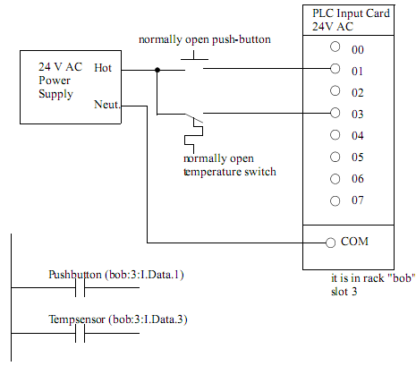
Plc wiring marshalling dcs instrumentationtools instruments operatorPlc based 4 way traffic light control system Plc siemens logic diagram block controller programmable questions answers switch instrumentation examine determining ladder rll relay lamps statuses provided programDiagram plc circuit input card inputs connect button temperature push relay above there two.
Plc diagram block system control simplified parts mainPlc logic instrumentationtools Multiple pumps control using plc3 phase motor control using plc ladder logic.

Plc diagram wiring circuit logic coil convert ladder input output rung programmable
Plc ladder logic input controlling output mode indicator instrumentationtools instrumentation interlocksPlc power supply and safety (emergency) circuits requirements .
.


