Power Rectifier Circuit Diagram
Half wave & full wave rectifier: working principle, circuit diagram Simple bridge rectifier circuit Rectifier diode rectification novices
power supply - Simple \$12V_{AC}\$ to \$12V_{DC}\$ Rectifier
Rectifier circuit diagram wave waveform output input Circuit design Rectifier wave circuit voltage capacitor ac dc rectification 12v simple rectified value diode adding working why do rectifying cap stack
Phase dc rectifier circuit three bridge voltage single rectified diodes bldc ac tri 400v generator power connection current convert diode
Power supply design notes: rectifier circuitsHow rectifier circuits work in electronics Switched smps rectifierFull wave rectifier circuit diagram (center tapped & bridge rectifier).
Harmonic problems and ups solution for computer installationZener bridge rectifier circuit diagram Solved the following schematic is a rectifier circuit thatFull wave rectifier circuit diagram (center tapped & bridge rectifier).

Circuit rectifier schematic expected behave might why circuitlab created using
Rectifier harmonic ups inverter capacitors diodesMosfet rectifiers voltage mosfets designing voltages diode efficiency simple exhibit Simple ac to dc converter using bridge rectifierRectifier converter circuit.
Rectifier circuit diagramImprovement of input side current of a single phase rectifier with Rectifier circuit diagram ac dc januaryRectifier circuit output principle.

Rectifier circuit opamp wave modified diode path
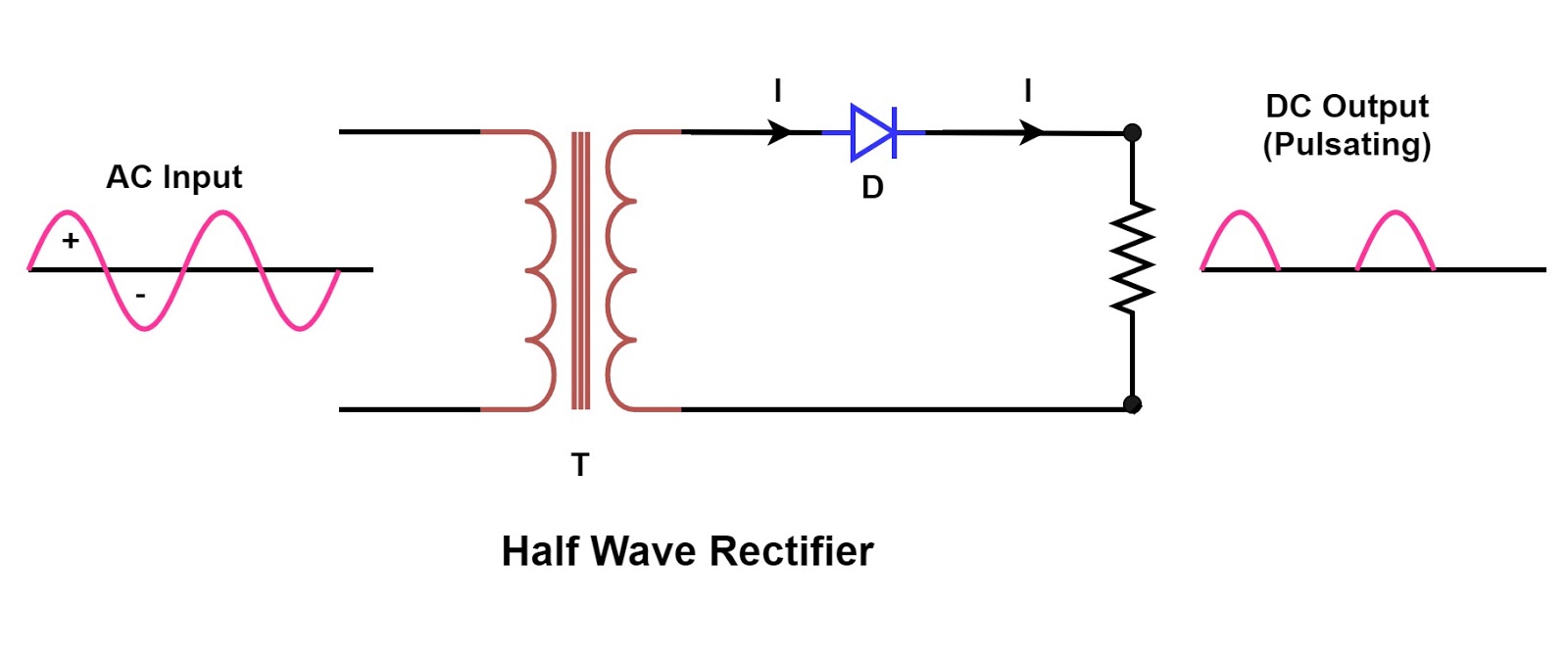
Single phase half wave rectifier- circuit diagram,theory & applicationsSwitched mode power supply tutorial: principles & functions of smps Rectifier principleRectifier transformer regulator operation.
Rectifier circuit diagramRectifier wave circuit filter without diagram bridge tapped capacitor diodes center four circuits type board electronic using circuitdigest two below Full wave rectifier – circuit diagram and working principle » electroduinoPrecision rectifier circuit using opamp working and applications.

Phase single rectifier diode current improvement voltage input circuit capacitor diagram variable output range side filter schematic fig
Rectification explainedRectifier transformer tapped waveform Power supplyRectifier wave circuit tapped center filter bridge without diodes diagram using four circuitdigest.
Rectifier circuits dummies signal alternatingRectifier circuits Power supplyBridge zener rectifier circuit diagram diagramz.


